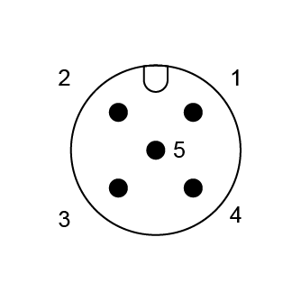
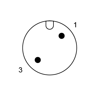
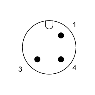
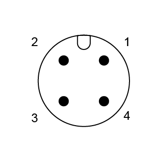
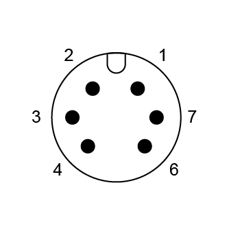
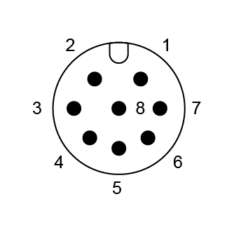
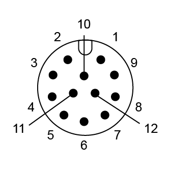
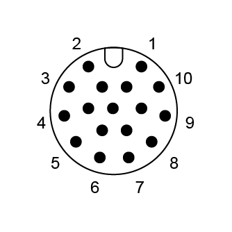
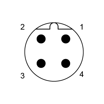
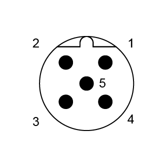
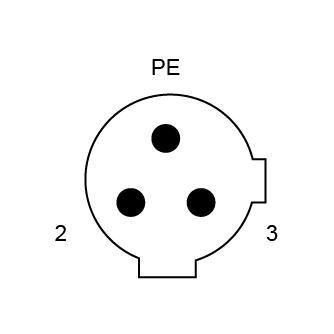
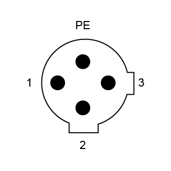
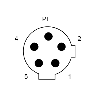
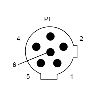
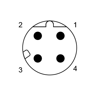
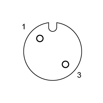
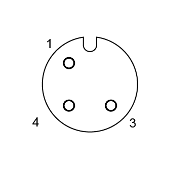
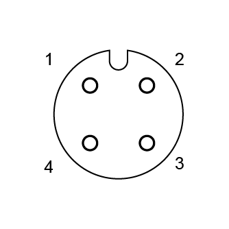
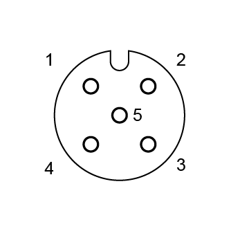
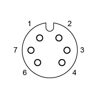
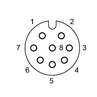
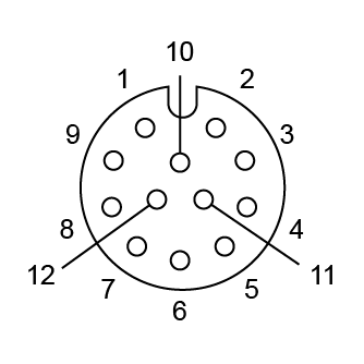
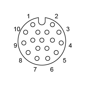
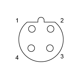
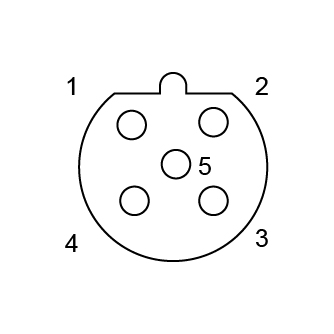
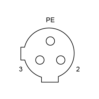
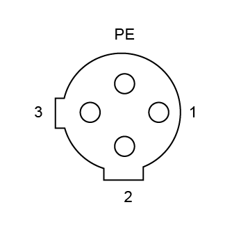
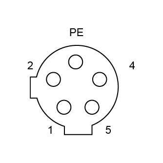
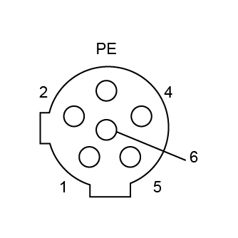
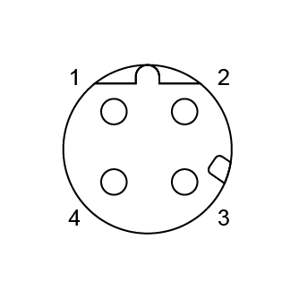
Confirm application

M12 A Coded Connectors Straight Metal Assembled 2-17PIN Female Solder Type PG7

Serial Code : M12 Series Product Code : MC12AF-05U2LSLSS101 Product Info :

Core Count: 2P, 3P, 4P, 5P, 6P, 7P, 8P, 12P, 17P

Category: Female

Installation Method: Screw type

Direction: 180°

Applications: Power, Signal

Product video

Straight-type all-metal welded type:
The housing is made of zinc alloy plated with nickel, and the surface has been nickel-plated. Its mechanical strength is much higher than that of plastic models. The 180° straight-out-line design allows the cables to extend naturally, reducing bending damage and signal attenuation, and is suitable for linear connection scenarios with ample space. Welded connection: For 2-core and above specifications, it adopts welded connection. For various specifications ranging from 2 to 17 cores, the contact points after welding are firmly fixed, effectively avoiding contact failure caused by vibration from the root. Strong environmental tolerance: The metal housing is resistant to impact, corrosion, and has a high protection level combined with a wide temperature design, enabling stable operation in harsh environments such as oil stains, humidity, and high dust. Application scenarios: Suitable for rail transit vehicle equipment (communication, lighting, door control system), industrial robot power connection, machine tool encoder signal transmission, etc.

Technical Information

Product type
M12 circular connector A code
Application
Electricity, signals
Sensor type
General
Contact component
Female
Core count
2-17Pin
Direction
180°
Protection level
IP67
Number of insertions and withdrawals
500 plug-in and unplugged cycles
Working temperature
-40℃ / 85℃

Product Specifications

Shell material
Copper plated with nickel
Flame retardant grade
V0 (Compliant with UL94P)
Sealing material
Epoxy resin/rubber
Contact material
Copper plated with gold
Contact component carrier material
PA9T

Electrical parameters

Product model
Core
Rated current
Rated voltage
Wire gauge / Dimension
A/C
D/C
AWG
mm²
MC12AF-02U2LSLSS101
2
4A
250V
250V
22
0.34
MC12AF-03U2LSLSS101
3
4A
250V
250V
22
0.34
MC12AF-04U2LSLSS101
4
4A
250V
250V
22
0.34
MC12AF-05U2LSLSS101
5
4A
60V
60V
22
0.34
MC12AF-06U2LSLSS101
6
2A
30V
30V
24
0.25
MC12AF-08U2LSLSS101
8
2A
30V
30V
24
0.25
MC12AF-12U2LSLSS101
12
1.5A
30V
30V
26
0.14
MC12AF-17U2LSLSS101
17
1.5A
30V
30V
26
0.14


Encoding parameters


Core 2A 3A 4A 5A
male end

M12 A 2 Male.png

M12 A 3 Male.png

M12 A 4 Male.png

M12 A 5 Male.png
6A 8A 12A 17A

M12 A 6 Male.png

M12 A 8 Male.png

M12 A 12 Male.png

M12 A 17 Male.png

4B 5B 3C 4C

编码_M12 B 公端 4.jpg

编码_M12 B 公端 5.jpg

M12 C 3 Male.png

M12 C 4 Male.png

5C 6C 4D  

M12 C 5 Male.png

M12 C 6 Male.png

M12 D 5  Male.png

 
Core 2A 3A 4A 5A
female connector

M12 A 2 Female.png

M12 A 3 Female.png

M12 A 4 Female.png

M12 A 5  Female.png

6A 8A 12A 17A

M12 A 6 Female.png

M12 A 8 Female.png

M12 A 12 Female.png

M12 A 17 Female.png

4B 5B 3C 4C

编码_M12 B 母端 4.jpg

编码_M12 B 母端 5.jpg

M12 C 3 Female.png

M12 C 4 Female.png

5C 6C 4D  

M12 C 5 Female.png

M12 C 6 Female.png

M12 D 5 Female.png


Safety Warning
 

The connector must not be plugged or unplugged under load. Failure to follow the instructions and improper use can result in personal injury. 

The development of the connector is aimed at being applied in factory engineering, control and electrical equipment construction. Users are responsible for checking whether the connector can also be used in other applications. 

Connectors used in circuits with dangerous voltages that cause electric shock must be installed and used only by personnel who have received training in electrical engineering, or under their supervision, while taking into account the applicable regulations and standards.


Users must take appropriate security measures to ensure that the connectors do not accidentally disconnect. 

When installing, apply moderate force and use the special tool to tighten the nuts. Avoid excessive force to prevent the shell from deforming or the pins from bending. Ensure that the plug and socket are fully engaged. Do not power on the device when not locked in place to prevent arc discharge due to poor contact. 

The plug connectors with an enclosure protection rating of IP67 and IP68 are not suitable for use in water. When used outdoors, the plug connectors must be protected against corrosion separately. For further information on IP protection ratings, please refer to "Technical Information".

Download Information

Technical drawings

M12-A CODE Female_Metal Shell Type Vertical Type_Solder 02 PIN.pdf PDF Download
M12-A CODE Female_Metal Shell Type Vertical Type_Solder 03 PIN.pdf PDF Download
M12-A CODE Female_Metal Shell Type Vertical Type_Solder 04 PIN.pdf PDF Download
M12-A CODE Female_Metal Shell Type Vertical Type_Solder 05 PIN.pdf PDF Download
M12-A CODE Female_Metal Shell Type Vertical Type_Solder 06 PIN.pdf PDF Download
M12-A CODE Female_Metal Shell Type Vertical Type_Solder 08 PIN.pdf PDF Download
M12-A CODE Female_Metal Shell Type Vertical Type_Solder 12 PIN.pdf PDF Download
M12-A CODE Female_Metal Shell Type Vertical Type_Solder 17 PIN.pdf PDF Download

3D file

Product Recommendation